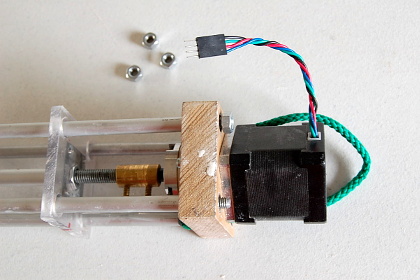
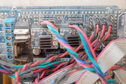
Digital Pots
Analogue Pots
Journal
2017
2016
Journal 2014
Journal 2014
Studio Journal 2013 - 12
2012 Journal
Self build 3D printer
Self build printhead
Learn Blender
 
Facebook Twitter Instagram Pinterest YouTube Google+


MAKE YOUR OWN CLAY AUGER PRINTHEAD WITH MECHANICAL RAM DELIVERY

This is a development on or an upgrade to the Make Your Own 3D Delta Printer for Ceramics first published in 2013. It consists of an auger type stop start or retraction printhead with a mechanical ram clay delivery. This same printhead can be used with a compressed air clay delivery as developed by WASP that makes use of a Boilie Gun, used by carp fishermen for ground bait making.

I have a slightly reduced size Delta that I travel with but then have always needed to make sure that I have compressed air available for the clay delivery. So I have long wanted to develop an all mechanical system and this is the result. As always my over riding criteria was to keep things simple. I did not want extra electronic controls or the need to go to a higher voltage.  It is designed around kit I already had such as the Techncon dispensing cartridge and upgrades the nonstop glue gun type printhead of the original 2013 JK Delta printer design.


PRINTHEAD


Printhead introduction –
The overriding design principal with this printhead was that it would be easy to take apart to clean and maintain. I do not like plastic printed parts as I have not found them to be strong enough and why go to that length if the parts can be kept this simple. The body of the printhead is engineering nylon. My choice of this material is because clay is incredibly abrasive, so I wanted to avoid metal and with my basic hand tools I can easily cut and drill this material. The auger screw fits snugly down the middle while being free to turn. I use different sized screws depending on what scale of printer and size of extrusion or nozzle I intend to use. If the screw bore is too big it is easy to get pulsing in the extrusion that textures the print surface. If too small you do not get enough flow or the motor is turning so fast it heats up over a lengthy print. My judgement for these decisions is not very measured but a mix of intuition and suck it and see, combined with what parts I can source easily.
The stepper motor probably does not need to be as powerful as those used to move the delta printer arms but I have always used similar motors. The motor wires plug into the E pins on the Ramps board with corresponding driver and power adjustment screw.
I have use the same design of printhead with clay piped in from a compressed air and mechanical ram driven delivery system with little noticeable difference.

Clay auger 3D printhead - Jonathan Keep


Auger screw –
The stepper motor I use is a SY42STH47-1684A High Torque Hybrid Stepper Motor. Four lengths of M3 threaded rod are bolted into the stepper motor to connect the motor to the nylon body. The length of these are determined by the beam coupling that is used to connect the motor drive shaft to the auger screw. (Different sized beam couplings are available). A hose clamp is used to clamp the M3 spacer rods to the nylon body cylinder. The nylon body cylinder is the same diameter as the glue gun extruder of the original JK Delta design so that it could be interchangable. If this is not necessary a body diameter of around 40 – 45 mm is a good idea so there is enough body material to drill the holes necessary for the auger screw and clay inlet pipe. Also this diameter of body cylinder can be securely attached to the printers printhead plate. I have varied the nylon cylinder length depending on the weight of auger - between 50mm for a small 6mm screw and 70 mm long for a larger 8mm screw. The screw length is determined by the length of the body cylinder. I aim to have the tip of the screw ending as close to the nozzle as possible. Obviously a hole the diameter of your screw is drilled in the vertical centre of the nylon body cylinder. (A wood drill bit will do this)
I put a rubber tap washer on the shaft of the screw up against the coupling that will then touch down on the top of the nylon body when the printhead is clamped together (not in all photos) to help keep clay pressure down the central shaft. Although the turn of the screw will be driving clay down I feel it is favourable to have the clay feed under more pressure than the screw will naturally take to help force the clay extrusion.


Clay auger 3D printhead - Jonathan Keep


Feed pipe –
I have tried various feed pipe attachments. Push connectors clog up with clay and stop working. Threaded connectors are a pain to undo. This simple wire pin through the pipe does the job. The clay feed pipe I use is 12mm natural nylon pneumatic airline pipe. I use this as I believe it to be more slippery than softer types of plastic pipe. Watch that you get 10mm inside measurement or the pipe is too stiff - a down side is this pipe does tend to kink.
A 12 mm hole is drilled into the side of the nylon cylinder body to take the feed pipe. This hole is drilled at least the width of your hose clamp down from the top of the nylon body and far enough in to connect with the vertical screw channel.
With the feed pipe in place I drill a vertical hole to take the wire pin that keeps the feed pipe in place. This vertical hole I drill the full length of the body cylinder so clay can be cleaned out of this hole. If not the pin will not go down after a while. An old bicycle spoke makes for a good pin.

Clay auger 3D printhead - Jonathan Keep


Nozzle –
I use a range of nozzle sizes depending on what I am doing so I have kept to a standard ¼ inch threaded outlet hole underneath the printhead. The central hole is drilled bigger and a ¼” tap used to create the thread. This gives the option of attaching a male Luerlock fitment that will take the range of Luer Lock dispensing tips or larger ¼” dispensing nozzles. I do like a metal nozzle tip so I customise my own nozzles. Nozzles will range from 1.2mm up to 4mm with 2.5mm being my standard.


Parts –
1 x Nema 17 Stepper Motor
4 x 70mm M3 threaded rod
4 x M3 nuts
1 x Flexible beam coupling
1 x rubber tap washer
1 x 6mm roofing screw
1 x 55mm length 45mm diameter engineering nylon rod
1 x Worm drive hose clamp 50mm dia
1 x 25cm natural nylon pneumatic airline pipe 12mm OD/10mm ID
1 x ¼” male Luerlock connector fitment
1 x Luerlock dispensing tip – Olive Green cut to 2.5 mm opening


Clay auger 3D printhead - Jonathan Keep


The screws are standard and I get them from my local hardware shop. To improve the efficiency I grind the tread deeper with an angle grinder and then cut the screws to the required length.


Clay 3D auger printhead - Jonathan Keep

MECHANICAL RAM

Mechanical ram introduction –
This design is not ideal in that the clay container could do with being larger but I am working on this. Currently it will holding enough clay for around three cups or one medium sized vase so it is a good starting point. Also the clay cartridges are high density polyethylene plastic and will expand under pressure if hard clay is used but they are reasonably inexpensive and translucent so you can see where the plunger is. The whole unit has to be quite lengthy and is then cumbersome to attach to your 3D printer. My best solution has been to hang it vertically with a counterbalanced as this allows for enough free movement particularly in the initial homing and start to print on a delta printer.
It is designed to be easily remove from the printer and to change the cartridge. I use clay of the same consistence as I would for a compressed air delivery system and that is about the consistency of toothpaste.
The auger screw extrusion and plunger ram are working in unison from the same gcode so there is no danger of too much pressure building up, if one stops they both stop. The down side is the balance between the clay delivery, the ram and the clay extrusion, the screw is set at the time of slicing the gcode and while the overall flow can be changed on the fly when printing the relationship or setting between the two elements creating the flow cannot. This is not a problem once you have a successful profile setup in your slicing software.

Clay mechanical ram - Jonathan Keep


The clay containers are 355ml/12ounce Techncon HDPE Dispensing Cartridge (TS120C) with outer diameter of 43mm and inner diameter of 40mm. They are 313mm long with a 1/4" NPT (6mm) female threaded outlet. The connection to the auger printhead is made with a 250mm length of nylon pneumatic airline pipe of 12mm OD/10mm ID. At my local plumbing supply I found a short length of brass 1/4" threaded tube that makes the link between cartridge outlet and nylon pipe.

During operation the clay containers are held in a 680mm long rig. My construction is a little light weight in construction and as it is put under quite sum longitudinal pressure it is worth engineering it well. Mine is made with four lengths of aluminium tube intersected with three 20mm thick MDF blocks. Each block is 60mm square with the bottom end block centrally drilled to take the profile of the cartridge end. The middle block is drilled to the diameter of the cartridge and placed along the length to hold the top edge of the cartridge. The top end block is fashioned to take the stepper motor with gearbox. The corners of each block are drilled to pass through the four 680mm lengths of aluminium tube. These are drilled and pinned to be held in place. A 40 mm length of threaded rod has been screwed into the top end end of each aluminium tube to take the securing nuts that hold the motor block in place.

The motor is a Nema 17 Stepper Motor with a 27:1 Planetary Gearbox attached. The motor is secured to the end block with four 30mm long M3 bolts. The motor shaft of this is joined to a 310mm length of 8mm threaded rod - the thread looks to be 20 turns per 25mm. The joiner I have used is a kiln element joiner. The motor wire will need a joiner plug in it so the ram can be uncoupled from the printer for cartridge change over.

A nut on this threaded shaft pushes a plate that is held from spinning by being held by the four aluminium lengths. The sliding plate will want to spin because the nut is made to fit snugly in the centre of the plate. My sliding plate is made of 6mm thick clear plastic and the profile of the nut is cut in the middle. A metal square with a 8mm central hole is attached on the side away from the motor so the nut is kept in place.

So finally to the plunger construction that is made from a 290mm length of tube that will slide over the motor threaded shaft. The sliding plate pushes up against the end of this tube so there is a metal washer to reduce friction and ware. On the other end of the tube is the plunger. I originally printed this in plastic but the forces involved ripped the plastic so I have resorted to a 45mm long wooden plunger made from a 38mm diameter dowel - heavy duty broom handle. The end of this is rounded to the inside profile of the clay cartridge. An O-ring makes for a tight fit of the plunger inside the cartridge. Originally I had two O-rings but have found one to be quite adequate. The plunger is centrally drilled a little over half way through its length to take the plunger tube. This is then secured by drilling and pinning at right angles.

Clay mechanical ram - Jonathan Keep

Clay mechanical ram - Jonathan Keep

Ram ceramic 3D printer - Jonathan Keep

Clay mechanical ram - Jonathan Keep


  Parts –
1+ x 355ml/12ounce Techncon Cartridge
1 x 250mm length of nylon pipe of 12mm OD/10mm ID
1 x 1/4" threaded brass tube
4 x 680mm aluminium tube
4 x 40mm threaded rod
4 x nut to fit threaded rod
3 x 20x60x60 mm MDF blocks
1 x Nema 17 Stepper Motor with a 27:1 Planetary Gearbox
4 x 30mm M3 bolts
1 x 310mm 8mm threaded rod
1 x nut for threaded rod
1 x metal washer for threaded rod
1 x joiner for motor shaft to threaded rod
1 x 6x60x60mm plastic slider plate
1 x 3x3mm metal plate
1 x 290mm plunger tube to fit over threaded rod
1 x 45mm wood plunger 38mm diameter
1 x O-ring to fit plunger


SETTINGS


Ramps board –
So now you have two stepper motors, one from the auger and one from the ram that need to be connecting to your Ramps Board. This board sits over the Arduino and along with the LCD screen makes up your electronic controller. On the ramps board there are connector pins and drivers, E0 and E1. E represents the feed rate in the gcode andit is the speed the material being printed is feed to the printhead. Plug the auger motor into E0 and the Ram motor into E1. Tune the motor driveres as required.
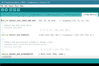
Marlin Firmware –
If you were to use the Marlin Firmware from the original 2013 JK delta the ram and auger will turn at the same speed according to the filament flow rate set when slicing. You will need to use the latest version of Marlin as this allows for the use of the gcode M163 that can set a mix factor for the E0 and E1. I have a video here explaining the settings for the Marlin Firmware. Download the latest version of Marlin from their website and from the documentation on the Marlin Website and my video you should be able to set up your firmware. There is one point I would not have covered in the video and that is the need to increase the DEFAULT_AXIS_STEPS_PER_UNIT for the E0/E1 motors. This is found in Configuration.h, the only tab in marlin you should need to look at and is under ‘Movement Settings’. You are looking for #define DEFAULT_AXIS_STEPS_PER_UNIT {72, 72, 72, 100}. The bracketed numbers denote the X,Y,Z,E0/E1 number of steps. By changing the E0/E1 steps from 100 to 200 the auger and ram will turn twice as faster.

Slicing gcode –
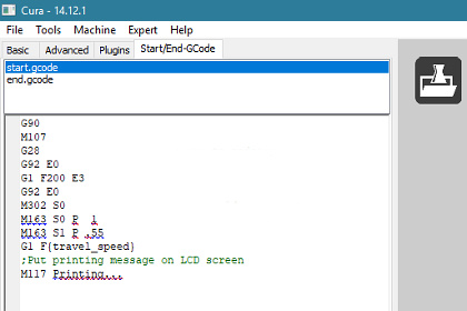
I use Cura as my slicing software and there is documentation here on how I set it up. Not covered is how to add the M163 gcode into the slicing header or start gcode. The image to the right image is how this should look. There is further reference here on the Marlin website. Confusingly the gcode line uses S0 for the E0 motor and S1 for the E1 motor. I have found that the ratio of a balance between the clay feed from the ram and clay extrusion from the auger can change from clay to clay and with different nozzles so you will need to experiment to find the best settings for your setup. I would suggest start with S0 P1 and S1 P1, an equal balance and go from there.

JK Delta settings - Jonathan Keep


Marlin Setting for Delta 3D Printer - Jonathan Keep


Cura setting for 3d Delta printer - Jonathan Keep


Google+